


Benedikt Breuer
Intl. Key Account Manager HFC Networks at Axing Group
Advantages with decentralized headend
The growing demand for broadband connectivity for businesses and private households poses great challenges for network operators and local suppliers, while at the same time offering great opportunities to develop new markets and retain customers. By using innovative solutions for Internet, telecommunications and TV supply, regional network operators and municipal utilities are able to offer highly competitive services on their existing coaxial or HFC infrastructures. A major evolutionary step in this context is the development away from traditional, centralised headends towards distributed headends, in which the RF signal generation is moved out of the headend and into the field. This approach to move signal generation to different locations (which may seem at first glance to be absurd) brings massive advantages. This article highlights the innovations of the recent history of broadband cable and the essential technical aspects of the Distributed-CCAP approach in general and of Remote-MACPHY or Remote-CCAP in particular.
Capacity increase with DOCSIS
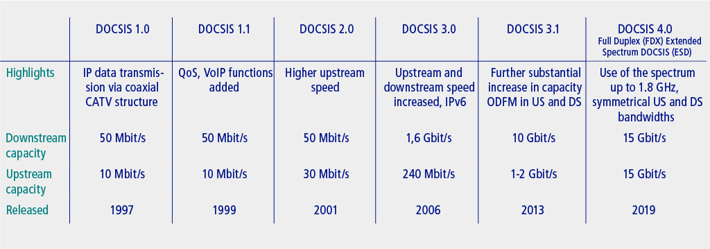
The DOCSIS protocol (Data Over Cable Service Interface Specification) has always been the basis for high bit-rate data transmission via coaxial cable or an HFC network. The DOCSIS standard has traditionally used the established and proven cable TV standards, i.e. DVB-C in Europe and Asia and J.83/B in North America, for the downstream RF transmission of IP data. QAM signals were also used upstream but extended by mechanisms for multiple access by many cable modems to few upstream frequency resources (TDMA, A-TDMA, S-CDMA). While the devices involved in the communication in DOCSIS 1.0, 1.1 and 2.0 were only in contact with each other via one single upstream and one single downstream, this changed fundamentally with DOCSIS 3.0. From now on, the cable modems (CM) on the customer side and the CMTS (Cable Modem Termination System) in the headend station could communicate via several upstream and downstream channels simultaneously, which catapulted the possible data rates to new heights, as shown in the following graphic:
OFDM (Orthogonal Frequency-Division Multiplexing)
The hunger for more bandwidth helped the technology to make the most significant innovation jump in the transition to DOCSIS 3.1 – the introduction of Orthogonal Frequency-Division Multiplexing (OFDM) in cable. This transmission technology, unlike the QAM used previously, is a multi-carrier technology in which data is split up into many orthogonal (i.e. not interfering with each other) sub-carriers that are very close to each other. In DOCSIS 3.1, this means up to 7600 carriers in downstream at intervals of only 25 kHz in so-called 8k mode and up to 3800 carriers at intervals of 50 kHz in 4k mode. Multiplying the subcarrier spacing and the number of carriers results in the maximum transmission bandwidth of a DOCSIS 3.1 downstream channel of 190 MHz (!) net. From now on OFDM is also used in the upstream but with channel bandwidths of maximum 96 MHz. Lower bandwidths are possible in both US and DS without any problems by not using all OFDM carriers. This reduces the data rate of the transmission in favour of less occupied bandwidth in the spectrum. For example, the minimum bandwidth of a DOCSIS 3.1 downstream signal is 24 MHz.
The use of OFDM in broadband coaxial cable was only logical, since it was possible to discover, study and use the advantages of this modulation with almost all modern transmission standards such as WiFi, LTE and 5G, DAB/DAB+, DVB-T/-T2, to name but a few.
The advantages result from the fact that in OFDM a signal with a high data rate is not modulated onto a single carrier, but onto many individual carriers transmitted in parallel with a very low individual data rate. A low data rate on the subcarriers has a positive effect on short-term interference, since only a few (possibly even only one) data symbols are destroyed. Together with a time and frequency interleaving (logically successive data are neither transmitted timewise directly one after the other nor on adjacent sub-carriers) and state-of-the-art forward error correction mechanisms, this results in an extremely robust transmission. A further advantage results if there are permanent interferences in the spectrum. Here, OFDM allows individual carriers to be excluded from transmission. Although this leads to a slightly lower overall data rate, it allows a stable data transport on all undisturbed subcarriers. In the case of QAM (high data rate on only one carrier), a single narrowband interferer can lead to an interruption of the data transmission of the entire channel.
The first efforts to establish OFDM in broadband cable were already made earlier in the form of DVB-C2 – here with a channel bandwidth of 8 MHz as usual for DVB-C. However, as DVB-C2 never became generally accepted, DOCSIS 3.1 is the first standard to use OFDM in broadband cable networks.
Improved forward error correction
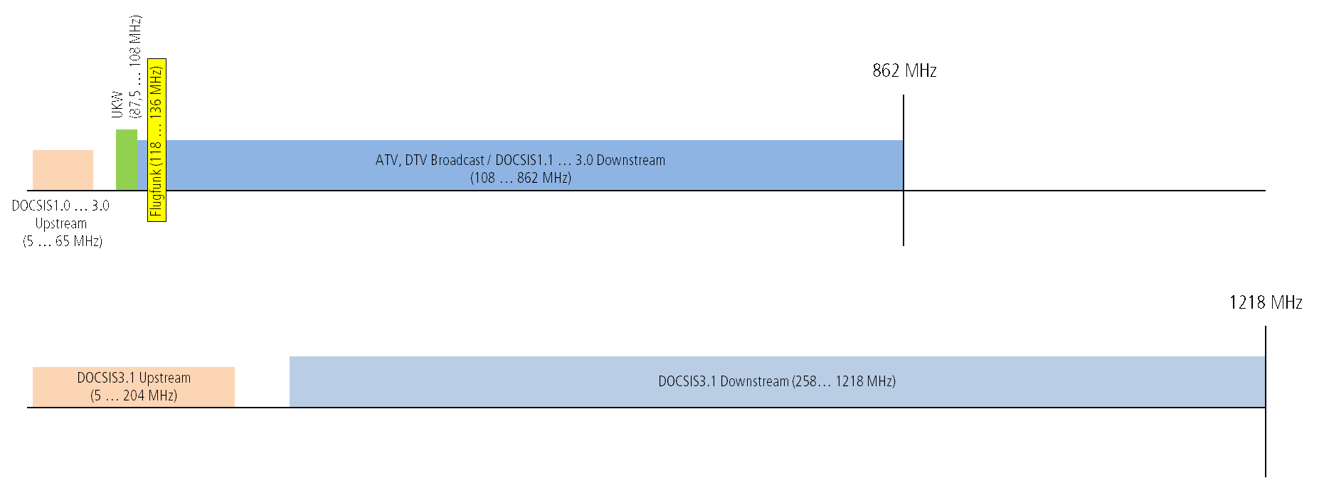
In addition to the use of OFDM and the new bandwidths of up to 190 MHz, an improved forward error correction is another characteristic of DOCSIS 3.1. LDPC (Low Density Parity Check) is now used, which is combined with BCH coding (Bose, Chaudhuri, Hocquenghem) in the downstream. The most groundbreaking innovation is the modulation order on the individual carriers of up to 4096 QAM (DVB-C and DOCSIS 3.0: max. 256 QAM). Together with the large total channel bandwidth, this means that a single DOCSIS 3.1 downstream can transport up to 2 Gbps. As with DOCSIS 3.0, channels can now also be bundled. With current CMTS generations, it is thus possible to feed 10 Gbps into the network on five downstream channels in the extended DOCSIS 3.1 frequency range from 258 MHz to 1218 MHz! In the upstream from 5 MHz to 204 MHz, a maximum of 2 Gbps is possible.
New band limits now arise in the spectrum. However, it is not absolutely necessary to upgrade your network; DOCSIS 3.1 can also be fed into the classic frequency ranges:
Changes in broadband cable
Recent developments in broadband cable have had a far-reaching impact on channel allocation. The switch-off of FM and analogue TV will eliminate FM carriers and 7 MHz channels. DOCSIS 3.1 breaks with the classical 8 MHz channel grid. The final consequence is a broadband cable spectrum with only a few OFDM channels:
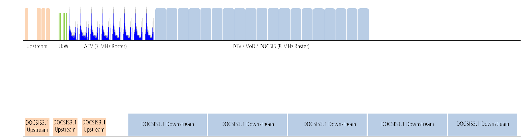
Of course, despite DOCSIS 3.1, you will still find parallel operation with classical DVB-C for TV supply (linear TV) and also with DOCSIS 3.0 in the 8 MHz grid for a long time, because you cannot or do not want to replace all the terminals in the field (TV sets, set-top boxes, cable modems) at once; and because conventional technology is also sufficient for many services (TV and “standard” data tariffs). However, DOCSIS 3.1 is already part of the future strategy of many network operators for high data tariffs beyond 400 Mbps, for example. A few operators, however, also rely on so-called “All-IP transmission”. This means that the entire spectrum, as shown in the last picture, is occupied with OFDM carriers and both Internet and television in the form of IPTV are made available to customers via this pure data connection!
It is now crucial for the success of the new DOCSIS standard to bring the promised data rates all the way to the customer. If it were so easy to transmit 4096 QAM, why hasn’t it already been done for a long time? The Distributed-CCAP approach is exactly the answer!
Independently of DCA (Distributed CCAP Architecture), the DOCSIS 3.1 standard itself already provides a feature that already allows modulations up to 1024 QAM with otherwise unchanged network structure, namely the more modern forward error correction (FEC). If a 256 QAM transmission currently functions stably with DVB-C or DOCSIS 3.0, which is the case in almost all networks, DOCSIS 3.1 will function reliably with 1024 QAM. This statement is permissible because of the system gain from the LDPC/BCH FEC. However, if you want to benefit fully from DOCSIS 3.1 and also want to transmit 2048 or 4096 QAM in the future, the 36 to 39 dB MER (Modulation Error Ratio), which is usually measured at the subscriber’s outlet, is not sufficient!
DCA is not only the right approach for a better RF performance on the customer side, but also for a reduction of the size of service groups. DOCSIS is a so-called shared medium. Only if the bandwidth in a network segment is not divided among too many households, high bit rate contracts with the consumer can be realized.
Improved MER quality through digital transmission to the node
The MER performance of the network at the user’s outlet, which is insufficient for the high modulation types, is due to the fact that the RF is generated in the headend station with a classic distribution structure. In the case of an HFC network, the RF is now transmitted into the field via an analogue-optical link. This analogue optic is chosen in order to be able to bridge longer distances with as little loss as possible. Of course, such a fibre-optic link is more loss-free than transmission via coaxial cable, where an amplifier must be installed every 200 to max. 400 meters due to the high attenuation of the cables. But an analogue-optical link also leads to a decrease of the signal quality! After the optical-electrical conversion of the broadband signal, a cascade of more or less many RF amplifiers usually follows before the signal is fed into the house distribution system via a tap and the building entry point. In case of a pure coaxial cable network, the analogue-optical link can also be omitted. However, regardless of the exact structure of the network, the RF transmitted from the headend station experiences a constant deterioration in quality during transmission up to the user’s socket.
In the case of DCA, the RF is only generated far out in the field in the digital access node. This means that from the headend station to the DCA node a digital link transports the content without loss in the form of Ethernet signals. The RF generated in the field now only has to bridge a cascade of a few amplifiers. This is known as the “last mile”. This leads to a significant improvement in signal quality at the user’s socket. In addition, as already mentioned, DCA makes it easier to reduce the size of service groups. Smaller service groups in combination with higher signal quality and thus higher modulations lead to a significantly increased bandwidth per user! Other advantages of DCA are less complexity and cheaper equipment in the headend, less space demands, lower energy consumption and lower requirements for cooling and air conditioning of the headend. A high degree of scalability makes the approach future-proof and competitive.
Now DCA essentially has two different approaches. Remote-PHY (RPD = Remote-PHY-Device) and Remote-MACPHY (RMD = Remote-MACPHY-Device). With RPD only the RF signal generation is outsourced to the access node. All other CMTS functionalities remain in the headend. This is reflected in the naming: Remote stands for “distant” or “outside” and PHY stands for “physical layer”, which corresponds to the bit transmission layer of the OSI reference model, i.e. in our case the generation of the QAM or OFDM signals. In the case of the Remote MACPHY, the MAC layer also moves to the remote node, which again leads to the corresponding naming.
The differences are illustrated again in the following figure:

The main problem with using Remote-PHY is that CMTS core functionality is still required in the headend. Although the communication between headend and RPD is standardized (DEPI, UEPI, GCP), communication between systems from different manufacturers is still complicated due to many optional and proprietary interpretations of the standards. It is a high effort to bring an RPD online and manage it.
With the RMD approach, all CMTS and DOCSIS functionalities are in the node, reducing the headend to inexpensive routing and switching hardware and software. Flexibility is also further increased because an RMD can communicate either with a simple switch or an OLT (Optical Line Terminal; if, for example, due to GPON activities of the operator, it is available anyway) in the headend and because there is no manufacturer lock-in!
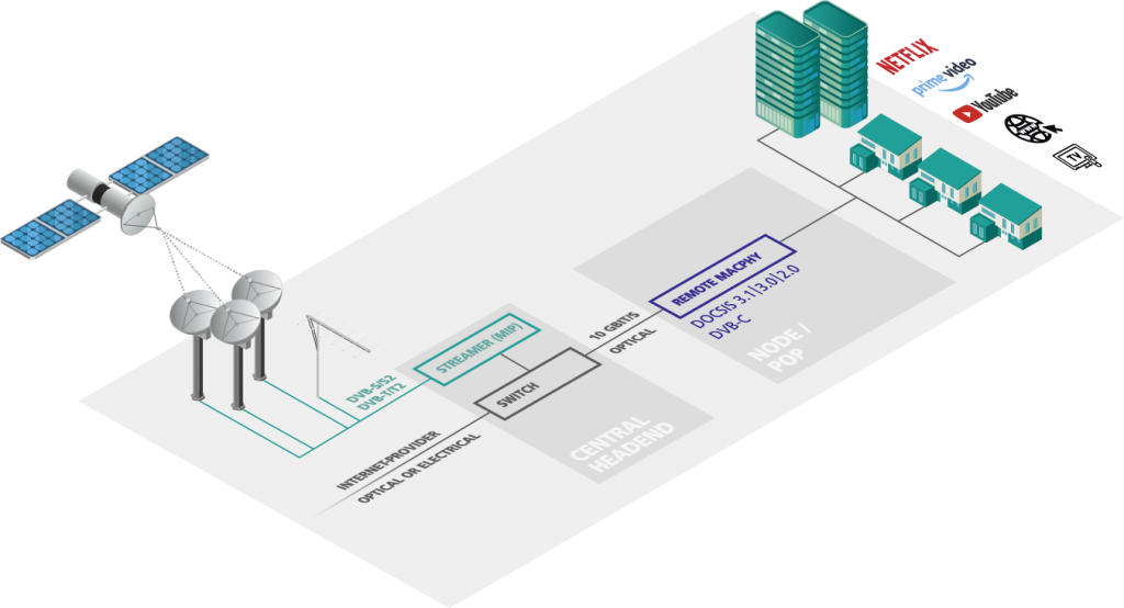
Generation of the DVB-C TV signal by Edge-QAM technology
If the node contains not only CMTS but also Edge-QAM functionality, i.e. DVB-C signal processing for TV signals, this is referred to as Remote-CCAP. If the TV content in the form of SPTS or MPTS data streams is sent from the headend to the node via the digital link, a Remote-CCAP is able to generate the entire broadband spectrum:
Conclusion
With Remote-MACPHY/CCAP, all key functions are no longer located in the headend station, but directly in the access node, i.e. in a highly integrated platform. The extremely cost-efficient solutions can be adapted precisely to customer requirements and are also scalable to future applications. The high flexibility of the systems, many possible migration scenarios from classic headend architecture to Distributed CCAP and the reusability of existing coaxial or HFC structures minimizes the investments required to offer multi-gigabit services.
There is no doubt that fibre optic will prevail in the long term and that new infrastructures to be built are generally fibre optic-based. However, many network operators, antenna communities, city carriers or even the housing industry are faced with the task of having to offer ever higher bandwidths to existing customers and on existing networks. The reasons for this are manifold – pressure from the customer side, competition from other broadband service providers, bandwidth as a location factor for the economy and European or national broadband targets are just some of the motivations. The decision to completely overbuild an existing and in principle well-functioning coaxial cable infrastructure with optical fibre and to offer true digital FTTH poses immense challenges onto operators. With Remote-CCAP, however, a fully mature, deliverable technology that has already been used thousands of times around the world is available to ensure that bandwidth requirements can be met in existing networks in the medium and long term. With manageable costs and short conversion times, the gigabit age can be heralded in. Remote-CCAP is therefore the alternative to PON and FTTH.